Thursday 8 December 2011

Systems and Control - Mini Test - Outcome 1 and 2

Here are the questions we looked at today in the mini test:


a) Closed loop control (continuous)
b) Negative Feedback
c) Error detector - to compare the actual temperature to the set temperature and send a signal to the control.  i.e. if the temperature is higher than the set level then a negative signal will be sent to the control, if the temperature is lower than the set level then a positive signal will be sent.
d) The desired temperature is set by the user.  The error detector then compares this set level to the actual temperature in the oven, sensed by the temperature sensor.  If it is too cold the error detector will send a positive signal to the control which will turn on the oven to heat up.  When it reaches the correct temperature there will be no difference between the set temperature and the sensed temperature and so the error detector will send a 0 signal to the control which will switch off the oven.  If it is too hot then the sensed temperature will be higher than the set temperature and the error detector will send a negative signal to the control which will keep the oven off.  This system of constantly monitoring the temperature will mean that the oven will maintain a constant temperature.
e) Thermistor


a) Open Loop Control
b)


a) Sequential Control - A series of events happen one after the other.  The end of one event signals for the start of the next.  So the green traffic light switching off will send the signal to switch on the amber light.

b) Continuous Control - This is a system where the input (temperature sensor) is sending information into the system all the time and the outputs (heater) are being controlled all of the time.  A change in the input directly results in a change in the output. In this example if it is sensed to be too hot, the heater will turn down, if it is sensed to be too cold the heater will be turned up, maintaining a constant temperature.

c) On/Off Control - The system can only ever be in one state: on or off, and nothing in between. This is the type of control used in the conveyor belt.  It will keep moving until a box is sensed and then the motor will switch off, stopping the belt.

Tuesday 15 November 2011

Systems and Control

Here is a quick break down of how to draw System Diagrams from last year as a reminder.

We will be looking at systems which use Microprocessors, but you could have electronic components or mechanical systems as your process as well.

Now we need to know about control diagrams as well.  These are similar in many ways to system diagrams, but they include an error detector as part of the control.

Control diagrams are mainly used to describe systems which have closed loop control.  That is that they self regulate the output.  This means that they need to include some sort of sensor to monitor what the output is doing. Open loop control systems have no ability to control the output any better than switching it on or off.  This can be seen in the lights in the classroom.  They do not dim when it is bright outside, they are switched on, and they stay on at the same brightness until they are switched off.  An oven, on the other hand uses closed loop control.  You set the temperature and it heats up until it is at that temperature, then the temperature in the oven is closely monitored and the heating element switched on and off to keep it as close to the set temperature as possible.

The error detector compares the sensed, actual value and the set/desired level and gives a signal accordingly.  Normally this signal would go either to the process, or to the control unit, depending on the level of detail required.  The diagram below shows only the process.


The diagram above shows a closed loop system using negative feedback. This means that it works to try to reduce the difference between the set/desired level and the actual level sensed by the output sensor - the error.  As shown above, if the actual temperature is too cold, the error detector will give a high signal, switching the heater on; if the temperature is too hot, the error detector will give a low signal and the heater will turn off.

This can also be shown in this graph:


You can see clearly that the system is trying to stay at the desired temperature, but the deign of the system means that as soon as it is too hot, the heater is switched off, but this takes some time to cool down.  When it is too cold it takes some time to warm up again.  The space on the graph that is above and below the desired temperature shows the error - the difference.  Negative feedback works to reduce this error.

Positive feedback is not often used.  It amplifies the error between what you want and what the sensed output is.  And so the error gets bigger and bigger.  This can be heard when you stand too close to the amp with an electric guitar and you get a giant squeal out of it!

There are three types of closed loop control you need to know about:

On/Off Control: The system can only ever be in one state: on or off, and nothing in between. This is the type of control used in the oven.  It is constantly switching on and off to try to keep the temperature to the desired level.

Continuous Control: This is a system where the inputs (often sensors) are sending information into the system all the time and the outputs are being controlled all of the time.  A change in the input directly results in a change in the output.  This is the type of control used in a robotic arm - a signal to tell the system where the desired position is given, this is compared to the signal from the arm sensor feeding back the actual position of the arm.  As the arm moves this position is fed back to the control until it is in the correct position and the arm stops moving.

Sequential Control: A series of events happen one after the other.  The end of one event signals for the start of the next.  This is the type of control used in a washing machine as it goes through the wash cycle.

Monday 7 November 2011

Today's Pneumatic Revision

1. Draw an air bleed circuit which would outstroke a single acting cylinder.


2. Show how a 5/2 valve can control a double acting cylinder. The signals to actuate the 5/2 valve should come from two 3/2 push button spring return valves.


3. Draw a circuit which will outstroke a single acting cylinder if a microswitch is pressed or a push button on a 3/2 valve is pressed


4/ Calculate the outstroke and instroke force of a cylinder of diameter 50mm and a rod diameter of 3mm.  The air pressure is 0.3 N/mm2

Monday 31 October 2011

Some More Pneumatics Revision

Today I set some dates so you know what is coming up homework-wise and NAB-wise. They are:

3/11/11 - Practice NAB in class to include both mechanisms and Pneumatics

7/11/11 - Pneumatics Homework to be handed in 
               (this is in the back of your booklet and should be answered on lined paper)
            - Also if you got less than 31 marks in the Mechanisms homework you need to resubmit this also 
              (remember to come in on Wednesday lunchtime for some extra help)

14/11/11 - Mechanisms and Pneumatics NAB

Today we looked at this circuit and answered the questions below.  Again I will leave the answers as a comment so that you can attempt the questions again first before reading.

Thursday 27 October 2011

Today's Pneumatic Revision

Today we looked at the following pneumatic circuit to check our understanding of pneumatics:


1. Give the full name of all the valves/components.
2. What function do the three highlighted sub-systems perform?
3. Describe the operation of the circuit.
4. If the double acting cylinder has a diameter of 30mm and a rod diameter of 5mm; and the supplied air pressure is 5N/mm, calculate:
      a) The outstroke force
      b) The instroke force

I will leave the answers as a comment so you can have a chance to answer the above questions before seeing them.

Wednesday 26 October 2011

Pneumatics

In this topic you need to be able to identify and describe pneumatic circuits and also, as for the NAB, draw these circuits from scratch.

It is therefore very important that you understand how to draw the symbols that you will need to use.

Cylinders:


You can see that the single acting cylinder has one input port which, when air flows in, will outstroke the cylinder.  The spring will make the cylinder instroke as soon as this input air stops.

The double acting cylinder has two input ports, one at each end. This means that air operates the cylinder  for both instroke and outstroke.

Valve Symbols:

The symbols for valves show where external connections (i.e. for main air or exhaust) are connected, as well as the internal connections for each state.


3/2 Valves:

3/2 valves are so called because they have 3 ports and two different states.  The symbol for a 3/2 valve is in two parts to show the two different states it can be in.  The bottom box typically shows the state a valve would be in when just out of the box, or unactuated.   This means that main air is not flowing into the valve, and any excess air in the system can escape out of the exhaust:


The top box is the "action" box.  This is when actuated the valve will allow main air to flow through the valve:

(note, that although I have added main air and exhaust here to help explain, all connections should be drawn on the bottom box.)

To finish your symbol you need to add the actuators.  The actuator make the box they are attached to "happen".  So in this case the push button actuates the valve and allows main air to flow from port 1 to 2.  The spring pushes the top back up again to block off main air when the button is released.

5/2 Valves:

5/2 valves are so called because they have 5 ports and 2 states.  They are primarily used to control a double acting cylinder as main air is always flowing through the 5/2 valve to hold the cylinder outstroke or instroke.  The change of state in a 5/2 valve simply means that main air flows from port 1 > 2 or port 1 > 4, unlike the 3/2 valve which either allowed main air to flow, or blocked it off.

State 1 > 2:


State 1 > 4:


5/2, lever lever valve controlling a double acting cylinder:

Note how all connections are drawn on the left hand box.

Unidirectional Flow Control Restrictors:

A unidirectional FCR combines a bi-directional FCR and a one way valve.  In the diagram below, if the air flows from right to left, it pushes the ball out of the one way valve and air can freely flow along the top of the Unidirectional FCR.  If the air flows from left to right the air pushes the ball into the one way valve which blocks it off and therefore the air is forced to go through the restrictor.

When using a FCR to control the speed of a cylinder it is important to remember to restrict the EXHAUST of the cylinder (the air coming out of the cylinder) so that the cylinder has full pressure air pushing it outstroke and the motion will be smooth with full force.  This is shown below so that the cylinder is being slowed down on outstroke, but will instroke full speed:


Note: just remember that the arrows for the one way valve point away from the cylinder.

Time Delay:


A reservoir can be added after an FCR to cause a time delay.  The air is restricted and therefore takes some time to fill up the reservoir causing the delay. The time can be adjusted by tightening or loosening the FCR or the size of the resistors.


For more information on AND and OR control, and an excellent interactive diagram please look at the BBC Bitesize website here.

Wednesday 12 October 2011

Today's Mini Test

Here are the questions and answers for today's mini test:

1. Name and draw the schematic diagram for two mechanisms which transmit motion through 90.

2. Name this mechanism and state its purpose:


Ratchet and Pawl - allows movement in one direction only.

3. Calculate the velocity ratio of this mechanism:


4. If the motor in the above system is turning at 500 rev/min, how fast is the output turning?

5. Work out the torque of this motor:


6. Calculate the reaction forces:


7. Name and draw three types of belt which could be used in a belt and pulley system.


8. What could you add to a belt and pulley system which has stretched and become loose?

Tensioner or jockey wheel

Tuesday 11 October 2011

Mechanisms

Most of mechanisms was covered last year in S3.  However we have learnt some new things this year:

Velocity Ratio/Linear Speed:
Like last year we had to use Velocity Ratios to work out rotational speed and we looked at how to then find the linear speed of a rope being wound around a drum.
Here are the two examples we looked at in class:
 
VR = 10/40 x 10/15
      = 1/6 (or 0.167)

SPEEDdrum = SPEEDmotor x VR
                     = 500 x 1/6
                     = 83.3 rev/min
                     = 1.39 rev/sec

C = Pi x D
   = 3.14 x 250
   = 785mm
   = 0.785m

SPEEDrope = SPEEDdrum x C
                    = 1.39 x 0.785
                    = 1.09 m/s

VR = 1/2 with 2 ropes

SPEEDload = SPEEDrope x VR
                    = 1.09 x 1/2
                    = 0.55 m/s  

 VR = 10/30 x 10/40
       = 1/12 (or 0.083)

SPEEDdrum = SPEEDmotor x VR
                     = 200 x 1/12
                     = 16.6 rev/min
                     = 0.27 rev/sec

C = π x D
   = 3.14 x 300
   = 942mm
   = 0.942m

SPEEDrope = SPEEDdrum x C
                    = 0.27 x 0.942
                    = 0.254 m/s


Moments:
A moment is the turning effect of a force.  Because a force is being applied to a system, it works like a lever.  So the further away from the pivot the force is applied the greater the moment.  Hence you calculate a moment:

Moment = Force x distance

Moments work on the principle of equilibrium. This means that as the system is not actually moving, all the forces and moments are balanced.  The three laws of equilibrium are:

ΣACM = ΣCWM
ΣFup = ΣFdown
ΣFleft = ΣFdown 

Using these laws we can find out unknown forces or distances.  These are the revision questions we looked at today:

Calculate the reaction forces in the car shown below.
First it might be useful to draw the Free Body diagram to show clearly how the forces are acting on the car.  However you will notice that you are given the mass of the people in the car, not their weight, therefore to find the forces the people will exert on car, you must use W = mg:

F90 = mg              F60 = mg
       = 90 x 9.81          = 60 x 9.81
       = 883N                = 589N

Now that you know the forces, you can start to use the laws of equilibrium.  Make R1 the pivot point so that you can work out R2:

Remember that a moment = force x distance from the pivot.  And you must work out all moments separately, you can't add them without multiplying them by their individual distances first.
  ΣACM = ΣCWM
R2 x 3.5 = (883 x 1) + (589 x 2.5)
    3.5R2 = 883 + 1472.5 
    3.5R2 = 2355.5
         R2 = 673N
 
Now that we know R2, we can use the equal forces law to work out R1.

      ΣFup = ΣFdown
 R1 + R2 = 883 + 589
R1 + 673 = 1472
          R1 = 799N

Then we looked at a car with a caravan on the back.  In this question the tow bar exerts a force both on the car and on the caravan. 
To tackle this question you must consider the car and the caravan separately.  First look at the caravan to work out the force in the tow bar P:
So if R3 is the pivot, you can see that the person is exerting a clockwise force and P an anticlockwise one.

  ΣACWM = ΣCWM
      P x 3.5 = 200 x 1
          3.5P = 200
               P = 57.1N

And using this we only have one unknown in the caravan.  So we can work out R3

      ΣFup = ΣFdown
          R3 = 57.1 + 200
               = 257.1N


Now we can work out the forces in the car.  This is the free body diagram for the car:
You will notice that as P is acting up from the car.  This is because there is tension in P and it is being stretched.  The internal forces act to keep P from stretching. So it acts away from both the car and the caravan.
We need to use moments to find the reaction forces.  I would start by making R1 the pivot, so that we can find R2:

                   ΣACWM = ΣCWM
(R2 x 2.5) + (P x 5.5) = 500 x 1
  2.5R2 + (57.1 x 5.5) = 500
               2.5R2 + 314 = 500
                         2.5R2 =  186
                              R2 = 93N

Now we can use the equilibrium in the vertical forces equation to find R1:
      ΣFup = ΣFdown
 R1 + R2 = 500
  R1 + 93 = 500
          R1 = 407N

The next question is slightly easier as it only involves one system, the desk.
Again, the best place to start is by drawing the free body diagram:
Taking moments about R1, we can find R2:

  ΣACWM = ΣCWM
      1 x R2  = (200 x 0.5) + (50 x 1.5)
             R2 = 100 + 75
             R2 =175N

Then using equilibrium in vertical forces we can find R1.
      ΣFup = ΣFdown
 R1 + R2 = 200 + 50
 R1 + 175 = 250
          R1 = 75N

Windlass:
A windlass uses a handle to magnify force.  This can be demonstrated using the Velocity Ratio equation:

Velocity Ratio = Distance moved by effort / Distance moved by load
The distances moved are found by working out the circumference (C = 2π r).  As the handle has a greater circumference you need to put in less force to lift the load when using the windlass.

Torque:

Torque is a turning force, or the turning effect of a force.  This means that when a force is applied to a gear or pulley it is magnified by the distance that force is applied is from the axle, i.e. the radius.  Thus, the bigger the pulley or gear, the bigger the Torque.
Therefore torque can be found using the equation:
         T = Fr
Where T is Torque and is measured in Nm, F is the force, and r is radius.

Power:
Power in mechanical systems are based on P = E/t.  Energy is force x distance and we base our power calculations on revolutions per second so time = 1.  Because this is a turning force we need to know the torque. And the distance is the number of revolutions per second.
Hence mechanical power:  P = 2πNT
P is power measured in W, N is number of turns (rev/s) and T is Torque.

Wednesday 5 October 2011

More Energy Practice

Today in the lunchtime drop in session we looked at the transfer of energy from one type to another.

This is the example we used. 


We had to find:
a) The total energy
b) The speed of the man 8m above the ground.

Answer:
a) The man at the top of the building is not moving so all of the energy he possesses is potential. This means that the total energy this man will ever have is equal to the potential energy at the top of the building as shown below.


b) At 8m above the ground the man now has some kinetic energy as he is falling and some potential energy as he is still above the ground.  The total energy the man possesses hasn't changed, only the way the energy is distributed.  Therefore the potential energy and the kinetic energy must add up to the total.  By working out the potential energy the man has a 8m we can then work out the kinetic energy as shown below.  When the kinetic energy is known, the velocity can be found, as shown below. 


Other Notes:
Other things people found confusing was the input energy produced by a fuel like petrol.  Fuel has an energy either per litre or per kg. Therefore the amount of fuel used must be multiplied by the energy stored in the fuel. 
So if petrol has 3.5MJ of energy per kg, and uses 2kg of fuel then the total energy supplied by the fuel is 3.5MJ x 2 = 7MJ.

People also found it difficult to work out which was the input energy and which was the output energy.  The only real rule in trying to work this out is to read the question carefully.  It will explain in the question how the system works.  It may also give you a diagram.  As a rule of thumb a system diagram will read input > process > output.  Therefore a diagram should be drawn in this order.

Other than the above: read the question, highlight and label all the relevant information so that it is clear what you know, and what you are aiming to find out.  Use the data booklet to help you work out what equation you need to use based on what information you have.

Thursday 22 September 2011

Energy Practice NAB

Today we did a practice NAB for your NAB on 27/9/11.  The questions are below and the answers in the pictures at the bottom with the mark allocation drawn on.

Energy Practice NAB

1. A sprung train barrier stops a 2000kg train traveling at 10m/s.  On impact the train exerts a force of 400kN on the barrier.  Calculate the following:
  a) The kinetic energy of the train before it hits the barrier
  b) The compression of the spring in the barrier once the train has stopped moving
  c) The speed of the train once it has collided with the barrier and continued to move after 100mm.

2. An energy audit is carried out on an electrical kettle connected to a 240V supply. The heating element has a resistance of 50Ω and the kettle took 3 minutes to boil 2 litres of water from a starting temperature of 80°c.  Calculate:
  a) The electrical energy going into the kettle
  b) The heat energy produced by the kettle
  c) The energy "lost"
  d) The efficiency of the system

These questions are of the same standard as the NAB, if you are happy with these and how to answer them you will be prepared for the NAB.  Revision of the homework is also a good way to ensure a thorough understanding.  If you were off today at FutureWise then I strongly suggest you come and get your homework marks back!

Here are the answers:


Friday 16 September 2011

Energy Revision

Energy is the ability to do "work".  Which means that it is what makes everything around us happen.  There are different types of energy.  We have been looking at some of the different types of energy and how energy can be transferred from one form to another.  This is a quick revision guide to what we have been doing in class.

Generally energy (or work done) can be found by multiplying the force by the distance it was exerted over, using the equation:
               E (wd) = F d (s)

Power is the rate at which energy is converted. This is another general energy question you need to be aware of. So power is the energy converted over time, or energy is power multiplied by time.
               E = Pt

Potential Energy is the energy a body possesses when it is positioned above the ground (datum) level, it is dependent on the weight (mass x g) x height:
               Ep = mgh

G is the acceleration due to gravity, so the rate at which we are being pulled towards earth.  It is a constant at 9.81 m/s/s on earth.


Kinetic Energy is movement energy.  The greater the mass and speed of a boy, the greater the kinetic energy.
             Ek = 1/2 mv2

Thermal Energy is heat energy.
             Eh = cmΔt 

C is the specific heat capacity of a material and it is constant.  For water C = 4190 J/KgK

Electrical Energy is based on the equations for electrical power, and the general energy power equation.
              E = Pt             P = VI    Therefore  Ee = VIt

Strain energy is the energy generated by stretching or compressing a spring.  First of all you may need to find the force required by multiplying the spring stiffness, in Newtons per millimetre, by the extension or compression.  This will give you the total force to use in the equation:
           Es = 1/2 Fx

Remember that although you need to use millimetres to find the force, x is measured in metres.

To find the efficiency of a system you must look at the energy in and the useful energy out.  Some energy will be "lost" i.e. the heat energy produced by a light bulb, or heat energy produced by friction in moving parts.
            n = Output Energy/Input Energy   (to make it a percentage, multiply by 100.

Thursday 15 September 2011

Today's Energy Mini Test

Here are the answers to today's mini test to help you prepare for the energy NAB.  Numbers in brackets are the marks allocated to each answer/line of working.  Remember that you get marks for working even if the answer is wrong, so make sure that you show clearly the stages you took.

1. State 3 renewable energy sources.
           Choose from geothermal, wind, hydro, solar, tidal/wave        (3)

2.a) Calculate the Spring Stiffness of a spring which was compressed 30mm by a 10N force.
            SS = Force / extension
                 = 0.3N/mm                               (1)

b) Calculate the strain energy of the above spring.
            Es = 1/2 F x                                    (1/2)
                 = 1/2 x 10 x 0.03                       (1/2)
                 = 0.15J                                       (1)

3.a) Calculate the kinetic energy of a ball (mass of 10kg) which is falling, if, at the top of the building it had a potential energy of 12kJ and now has a potential energy of 8kJ.
            Et = Ek + Ep                                   (1/2)
       1200 = Ek + 8000                                (1/2)
           Ek = 4000J (4kJ)                               (1)

b) What height is the ball at now?
           Ep = mgh                                        (1/2)
       8000 = 10 x 9.81 x h                           (1/2)
       8000 = 98.1 x h
            h = 8000/98.1
               = 81.5m                                        (1)

4. What is the acceleration due to gravity (g) on earth?
            9.81 m/s/s                                        (1)     

5. Calculate the speed of a lorry with a weight of 5000N and a kinetic energy of 6500J.
           m = w/g                (1/2)         Ek = 1/2 mv2                (1/2)
               = 5000/9.81      (1/2)      6500 = 1/2 x 510 x v2      (1/2)
               = 510kg              (1)                = 255
                                                           v2 = 6500/255
                                                               = 25.5
                                                           v = 5.05 m/s                   (1)

6. What is the mass of an object which has the potential energy of 7620J at a height of 3m?
         Ep = mgh                        (1/2) 
     7620 = m x 9.81 x 3            (1/2) 
              = m x 29.43
          m = 7620/29.43
              = 260kg                        (1)

7. Calculate the heat energy produced by an electric hair drier if it is 65% efficient and used 240V and 6A over 10 minutes.
     Ee = VIt                                (1/2)       Eh = 0.65 x Ee            (1/2)
          = 240 x 6 x (10 x 600)     (1/2)            = 0.65 x 864000    (1/2)
          = 864kJ                              (1)             = 562kJ                    (1)

Monday 11 July 2011

Summer Homework

Use the blog and your notes to answer these revision questions.  Make sure you label the questions clearly so it is easy to mark.  ATTEMPT ALL QUESTIONS!  You can always send me a message or write a comment below if you require more help with any of the questions.

Electronics:

1.  Draw a voltage divider which would act as a heat sensor.  Label all the components. Describe how the circuit works, mention temperature, resistance, and voltage.

2. For this transistor circuit, answer the following questions:


a)  As the light is on, the transistor must be fully switched on.  State the term used for fully switched on.
b) What is the base-emitter voltage (VBE) of the transistor in this state?
c) The signal from the microprocessor is 5v.  What is the voltage dropped over the base resistor?
d) What, therefore, is the base current which also flows through the base resistor?
e) If the transistor has a current gain (HFE) of 500, what is the current flowing through the lamp? (IC)
f) It is found that 9v is not enough for the lamp to shine it's brightest.  Draw a modified circuit which will allow the transistor circuit to still run on 9v and the lamp to use a new supply voltage of 240v.  Remember to draw all protective components required.  Label all components used.


3. For this motor and light series circuit work out the following:


a) The current in the circuit. (hint: remember P=IV)
b) The resistance of the motor (hint: remember that V=IR)

4. Using the log graphs for the different types of thermistors and the LDR work out the resistance for the following light levels/temperatures:
     a) Type 2 Thermistor at 75 degrees -
     b) Type 5 Thermistor at 60 degrees -
     c) Type 6 Thermistor at 250 degrees -
     d) LDR at 20 lux -
     e) LDR at 2 lux -
     f) LDR at 300 lux -

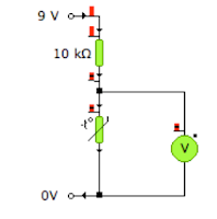
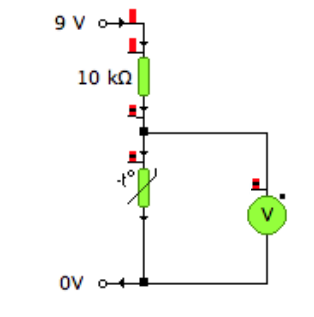
5. Consider these two circuits:

Circuit B
Circuit A


      a) State the name of this arrangement.
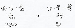
      b) Using the values you found in question 4, find the voltage out of
          circuit A for the following conditions:
           i) Type 2 Thermistor at 75 degrees -
           ii) Type 5 Thermistor at 60 degrees -
           iii) Type 6 Thermistor at 250 degrees -

     c) Using the values you found in question 4, find the voltage out of
         circuit B for the following conditions:
           i) LDR at 20 lux -

           ii) LDR at 2 lux -
           iii) LDR at 300 lux -

     d) For your answers above, if this was the signal to a transistor, state whether
          the transistor would be switched on or off.

Mechanisms

6. Draw a schematic diagram for and label mechanisms which will produce the following types of motion:
     a) Rotary to Rotary motion (two examples)
     b) Rotary to Rotary motion through 90 degrees (two examples)
     c) Rotary to Linear motion (one example)
     d) Rotary to Reciprocating (two examples)

7. State two mechanisms which will allow movement in one direction only/act as a break or safety feature in a system.

8. Consider this compound gear system:

Gear A is a worm gear
Gear B has 24 teeth
Gear C has 12 teeth
Gear D has 24 teeth

    a) Find the velocity ratio
    b) If the motor is turning at 1200rev/min, how fast is gear D turning.
    c) If gear B is turning clockwise, state the direction of gear C and D
    d) Over time the chain becomes loose and it starts to jump over the gears.
        What could be added to the system to ensure that this doesn't happen?


Logic 

9. A burglar alarm should sound if the master switch is on (1) and either a pressure pad next to the door is triggered (1) or the window is opened (0).
   a) Draw the truth table for this system
   b) Write the boolean expression from either your truth table or the English statement
   c) Draw a logic circuit which will fulfill this specification
   d) Suggest a component which could be added to ensure that the alarm
        stays on until reset.  Mark where this should be added with a cross.

10. Draw a block diagram for a system which uses logic to flash a light when it is dark.
      You will need to use: a light sensor, a Pulse Generator, and a lamp.  
                                        Choose the logic gate you will also require.

Pneumatics

11. Draw a 3/2 push button spring return valve. Include main air, exhaust and the port numbers.

12. Add to your question 11 drawing to show how two of these valves (above)
       could be connected to give AND control.

13. Consider this pneumatic circuit:


a) What is the full name of each of the components:
     i) Cylinder A
     ii) Valves B, C, D and E
b) Why are some of the connections dashed and some solid?
c) Describe the operation of the circuit
d) What type of motion does this circuit produce?
e) Draw the two components which could be added to give a delay before the
    cylinder instrokes.  Label them and describe how this works.

14. A double acting cylinder has a diameter of 20mm and a rod diameter of 5mm.
     a) If the air pressure is 4N/mm2 then work out:
         i) The force as the cylinder OUTSTROKES
         ii) The force as the cylinder INSTROKES
     b) Describe, which the use of diagrams, why the force is different on instroke to outstroke.