Monday 31 October 2011

Some More Pneumatics Revision

Today I set some dates so you know what is coming up homework-wise and NAB-wise. They are:

3/11/11 - Practice NAB in class to include both mechanisms and Pneumatics

7/11/11 - Pneumatics Homework to be handed in 
               (this is in the back of your booklet and should be answered on lined paper)
            - Also if you got less than 31 marks in the Mechanisms homework you need to resubmit this also 
              (remember to come in on Wednesday lunchtime for some extra help)

14/11/11 - Mechanisms and Pneumatics NAB

Today we looked at this circuit and answered the questions below.  Again I will leave the answers as a comment so that you can attempt the questions again first before reading.

Thursday 27 October 2011

Today's Pneumatic Revision

Today we looked at the following pneumatic circuit to check our understanding of pneumatics:


1. Give the full name of all the valves/components.
2. What function do the three highlighted sub-systems perform?
3. Describe the operation of the circuit.
4. If the double acting cylinder has a diameter of 30mm and a rod diameter of 5mm; and the supplied air pressure is 5N/mm, calculate:
      a) The outstroke force
      b) The instroke force

I will leave the answers as a comment so you can have a chance to answer the above questions before seeing them.

Wednesday 26 October 2011

Pneumatics

In this topic you need to be able to identify and describe pneumatic circuits and also, as for the NAB, draw these circuits from scratch.

It is therefore very important that you understand how to draw the symbols that you will need to use.

Cylinders:


You can see that the single acting cylinder has one input port which, when air flows in, will outstroke the cylinder.  The spring will make the cylinder instroke as soon as this input air stops.

The double acting cylinder has two input ports, one at each end. This means that air operates the cylinder  for both instroke and outstroke.

Valve Symbols:

The symbols for valves show where external connections (i.e. for main air or exhaust) are connected, as well as the internal connections for each state.


3/2 Valves:

3/2 valves are so called because they have 3 ports and two different states.  The symbol for a 3/2 valve is in two parts to show the two different states it can be in.  The bottom box typically shows the state a valve would be in when just out of the box, or unactuated.   This means that main air is not flowing into the valve, and any excess air in the system can escape out of the exhaust:


The top box is the "action" box.  This is when actuated the valve will allow main air to flow through the valve:

(note, that although I have added main air and exhaust here to help explain, all connections should be drawn on the bottom box.)

To finish your symbol you need to add the actuators.  The actuator make the box they are attached to "happen".  So in this case the push button actuates the valve and allows main air to flow from port 1 to 2.  The spring pushes the top back up again to block off main air when the button is released.

5/2 Valves:

5/2 valves are so called because they have 5 ports and 2 states.  They are primarily used to control a double acting cylinder as main air is always flowing through the 5/2 valve to hold the cylinder outstroke or instroke.  The change of state in a 5/2 valve simply means that main air flows from port 1 > 2 or port 1 > 4, unlike the 3/2 valve which either allowed main air to flow, or blocked it off.

State 1 > 2:


State 1 > 4:


5/2, lever lever valve controlling a double acting cylinder:

Note how all connections are drawn on the left hand box.

Unidirectional Flow Control Restrictors:

A unidirectional FCR combines a bi-directional FCR and a one way valve.  In the diagram below, if the air flows from right to left, it pushes the ball out of the one way valve and air can freely flow along the top of the Unidirectional FCR.  If the air flows from left to right the air pushes the ball into the one way valve which blocks it off and therefore the air is forced to go through the restrictor.

When using a FCR to control the speed of a cylinder it is important to remember to restrict the EXHAUST of the cylinder (the air coming out of the cylinder) so that the cylinder has full pressure air pushing it outstroke and the motion will be smooth with full force.  This is shown below so that the cylinder is being slowed down on outstroke, but will instroke full speed:


Note: just remember that the arrows for the one way valve point away from the cylinder.

Time Delay:


A reservoir can be added after an FCR to cause a time delay.  The air is restricted and therefore takes some time to fill up the reservoir causing the delay. The time can be adjusted by tightening or loosening the FCR or the size of the resistors.


For more information on AND and OR control, and an excellent interactive diagram please look at the BBC Bitesize website here.

Wednesday 12 October 2011

Today's Mini Test

Here are the questions and answers for today's mini test:

1. Name and draw the schematic diagram for two mechanisms which transmit motion through 90.

2. Name this mechanism and state its purpose:


Ratchet and Pawl - allows movement in one direction only.

3. Calculate the velocity ratio of this mechanism:


4. If the motor in the above system is turning at 500 rev/min, how fast is the output turning?

5. Work out the torque of this motor:


6. Calculate the reaction forces:


7. Name and draw three types of belt which could be used in a belt and pulley system.


8. What could you add to a belt and pulley system which has stretched and become loose?

Tensioner or jockey wheel

Tuesday 11 October 2011

Mechanisms

Most of mechanisms was covered last year in S3.  However we have learnt some new things this year:

Velocity Ratio/Linear Speed:
Like last year we had to use Velocity Ratios to work out rotational speed and we looked at how to then find the linear speed of a rope being wound around a drum.
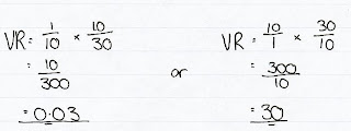
Here are the two examples we looked at in class:
 
VR = 10/40 x 10/15
      = 1/6 (or 0.167)

SPEEDdrum = SPEEDmotor x VR
                     = 500 x 1/6
                     = 83.3 rev/min
                     = 1.39 rev/sec

C = Pi x D
   = 3.14 x 250
   = 785mm
   = 0.785m

SPEEDrope = SPEEDdrum x C
                    = 1.39 x 0.785
                    = 1.09 m/s

VR = 1/2 with 2 ropes

SPEEDload = SPEEDrope x VR
                    = 1.09 x 1/2
                    = 0.55 m/s  

 VR = 10/30 x 10/40
       = 1/12 (or 0.083)

SPEEDdrum = SPEEDmotor x VR
                     = 200 x 1/12
                     = 16.6 rev/min
                     = 0.27 rev/sec

C = π x D
   = 3.14 x 300
   = 942mm
   = 0.942m

SPEEDrope = SPEEDdrum x C
                    = 0.27 x 0.942
                    = 0.254 m/s


Moments:
A moment is the turning effect of a force.  Because a force is being applied to a system, it works like a lever.  So the further away from the pivot the force is applied the greater the moment.  Hence you calculate a moment:

Moment = Force x distance

Moments work on the principle of equilibrium. This means that as the system is not actually moving, all the forces and moments are balanced.  The three laws of equilibrium are:

ΣACM = ΣCWM
ΣFup = ΣFdown
ΣFleft = ΣFdown 

Using these laws we can find out unknown forces or distances.  These are the revision questions we looked at today:

Calculate the reaction forces in the car shown below.
First it might be useful to draw the Free Body diagram to show clearly how the forces are acting on the car.  However you will notice that you are given the mass of the people in the car, not their weight, therefore to find the forces the people will exert on car, you must use W = mg:

F90 = mg              F60 = mg
       = 90 x 9.81          = 60 x 9.81
       = 883N                = 589N

Now that you know the forces, you can start to use the laws of equilibrium.  Make R1 the pivot point so that you can work out R2:

Remember that a moment = force x distance from the pivot.  And you must work out all moments separately, you can't add them without multiplying them by their individual distances first.
  ΣACM = ΣCWM
R2 x 3.5 = (883 x 1) + (589 x 2.5)
    3.5R2 = 883 + 1472.5 
    3.5R2 = 2355.5
         R2 = 673N
 
Now that we know R2, we can use the equal forces law to work out R1.

      ΣFup = ΣFdown
 R1 + R2 = 883 + 589
R1 + 673 = 1472
          R1 = 799N

Then we looked at a car with a caravan on the back.  In this question the tow bar exerts a force both on the car and on the caravan. 
To tackle this question you must consider the car and the caravan separately.  First look at the caravan to work out the force in the tow bar P:
So if R3 is the pivot, you can see that the person is exerting a clockwise force and P an anticlockwise one.

  ΣACWM = ΣCWM
      P x 3.5 = 200 x 1
          3.5P = 200
               P = 57.1N

And using this we only have one unknown in the caravan.  So we can work out R3

      ΣFup = ΣFdown
          R3 = 57.1 + 200
               = 257.1N


Now we can work out the forces in the car.  This is the free body diagram for the car:
You will notice that as P is acting up from the car.  This is because there is tension in P and it is being stretched.  The internal forces act to keep P from stretching. So it acts away from both the car and the caravan.
We need to use moments to find the reaction forces.  I would start by making R1 the pivot, so that we can find R2:

                   ΣACWM = ΣCWM
(R2 x 2.5) + (P x 5.5) = 500 x 1
  2.5R2 + (57.1 x 5.5) = 500
               2.5R2 + 314 = 500
                         2.5R2 =  186
                              R2 = 93N

Now we can use the equilibrium in the vertical forces equation to find R1:
      ΣFup = ΣFdown
 R1 + R2 = 500
  R1 + 93 = 500
          R1 = 407N

The next question is slightly easier as it only involves one system, the desk.
Again, the best place to start is by drawing the free body diagram:
Taking moments about R1, we can find R2:

  ΣACWM = ΣCWM
      1 x R2  = (200 x 0.5) + (50 x 1.5)
             R2 = 100 + 75
             R2 =175N

Then using equilibrium in vertical forces we can find R1.
      ΣFup = ΣFdown
 R1 + R2 = 200 + 50
 R1 + 175 = 250
          R1 = 75N

Windlass:
A windlass uses a handle to magnify force.  This can be demonstrated using the Velocity Ratio equation:

Velocity Ratio = Distance moved by effort / Distance moved by load
The distances moved are found by working out the circumference (C = 2π r).  As the handle has a greater circumference you need to put in less force to lift the load when using the windlass.

Torque:

Torque is a turning force, or the turning effect of a force.  This means that when a force is applied to a gear or pulley it is magnified by the distance that force is applied is from the axle, i.e. the radius.  Thus, the bigger the pulley or gear, the bigger the Torque.
Therefore torque can be found using the equation:
         T = Fr
Where T is Torque and is measured in Nm, F is the force, and r is radius.

Power:
Power in mechanical systems are based on P = E/t.  Energy is force x distance and we base our power calculations on revolutions per second so time = 1.  Because this is a turning force we need to know the torque. And the distance is the number of revolutions per second.
Hence mechanical power:  P = 2πNT
P is power measured in W, N is number of turns (rev/s) and T is Torque.

Wednesday 5 October 2011

More Energy Practice

Today in the lunchtime drop in session we looked at the transfer of energy from one type to another.

This is the example we used. 


We had to find:
a) The total energy
b) The speed of the man 8m above the ground.

Answer:
a) The man at the top of the building is not moving so all of the energy he possesses is potential. This means that the total energy this man will ever have is equal to the potential energy at the top of the building as shown below.


b) At 8m above the ground the man now has some kinetic energy as he is falling and some potential energy as he is still above the ground.  The total energy the man possesses hasn't changed, only the way the energy is distributed.  Therefore the potential energy and the kinetic energy must add up to the total.  By working out the potential energy the man has a 8m we can then work out the kinetic energy as shown below.  When the kinetic energy is known, the velocity can be found, as shown below. 


Other Notes:
Other things people found confusing was the input energy produced by a fuel like petrol.  Fuel has an energy either per litre or per kg. Therefore the amount of fuel used must be multiplied by the energy stored in the fuel. 
So if petrol has 3.5MJ of energy per kg, and uses 2kg of fuel then the total energy supplied by the fuel is 3.5MJ x 2 = 7MJ.

People also found it difficult to work out which was the input energy and which was the output energy.  The only real rule in trying to work this out is to read the question carefully.  It will explain in the question how the system works.  It may also give you a diagram.  As a rule of thumb a system diagram will read input > process > output.  Therefore a diagram should be drawn in this order.

Other than the above: read the question, highlight and label all the relevant information so that it is clear what you know, and what you are aiming to find out.  Use the data booklet to help you work out what equation you need to use based on what information you have.