Electronics:
1. Draw a voltage divider which would act as a heat sensor. Label all the components. Describe how the circuit works, mention temperature, resistance, and voltage.
2. For this transistor circuit, answer the following questions:
a) As the light is on, the transistor must be fully switched on. State the term used for fully switched on.
b) What is the base-emitter voltage (VBE) of the transistor in this state?
c) The signal from the microprocessor is 5v. What is the voltage dropped over the base resistor?
d) What, therefore, is the base current which also flows through the base resistor?
e) If the transistor has a current gain (HFE) of 500, what is the current flowing through the lamp? (IC)
f) It is found that 9v is not enough for the lamp to shine it's brightest. Draw a modified circuit which will allow the transistor circuit to still run on 9v and the lamp to use a new supply voltage of 240v. Remember to draw all protective components required. Label all components used.
3. For this motor and light series circuit work out the following:
a) The current in the circuit. (hint: remember P=IV)
b) The resistance of the motor (hint: remember that V=IR)
4. Using the log graphs for the different types of thermistors and the LDR work out the resistance for the following light levels/temperatures:
a) Type 2 Thermistor at 75 degrees -
b) Type 5 Thermistor at 60 degrees -
c) Type 6 Thermistor at 250 degrees -
d) LDR at 20 lux -
e) LDR at 2 lux -
f) LDR at 300 lux -
5. Consider these two circuits:
 | |
| Circuit B |
 |
| Circuit A |
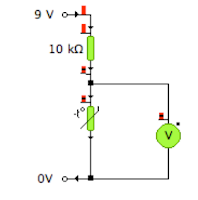
a) State the name of this arrangement.
b) Using the values you found in question 4, find the voltage out of
circuit A for the following conditions:
i) Type 2 Thermistor at 75 degrees -
ii) Type 5 Thermistor at 60 degrees -
iii) Type 6 Thermistor at 250 degrees -
c) Using the values you found in question 4, find the voltage out of
circuit B for the following conditions:
i) LDR at 20 lux -
ii) LDR at 2 lux -
iii) LDR at 300 lux -
d) For your answers above, if this was the signal to a transistor, state whether
the transistor would be switched on or off.
Mechanisms
6. Draw a schematic diagram for and label mechanisms which will produce the following types of motion:
a) Rotary to Rotary motion (two examples)
b) Rotary to Rotary motion through 90 degrees (two examples)
c) Rotary to Linear motion (one example)
d) Rotary to Reciprocating (two examples)
7. State two mechanisms which will allow movement in one direction only/act as a break or safety feature in a system.
8. Consider this compound gear system:
Gear A is a worm gear
Gear B has 24 teeth
Gear C has 12 teeth
Gear D has 24 teeth
a) Find the velocity ratio
b) If the motor is turning at 1200rev/min, how fast is gear D turning.
c) If gear B is turning clockwise, state the direction of gear C and D
d) Over time the chain becomes loose and it starts to jump over the gears.
What could be added to the system to ensure that this doesn't happen?
Logic
9. A burglar alarm should sound if the master switch is on (1) and either a pressure pad next to the door is triggered (1) or the window is opened (0).
a) Draw the truth table for this system
b) Write the boolean expression from either your truth table or the English statement
c) Draw a logic circuit which will fulfill this specification
d) Suggest a component which could be added to ensure that the alarm
stays on until reset. Mark where this should be added with a cross.
10. Draw a block diagram for a system which uses logic to flash a light when it is dark.
You will need to use: a light sensor, a Pulse Generator, and a lamp.
Choose the logic gate you will also require.
Pneumatics
11. Draw a 3/2 push button spring return valve. Include main air, exhaust and the port numbers.
12. Add to your question 11 drawing to show how two of these valves (above)
could be connected to give AND control.
13. Consider this pneumatic circuit:
a) What is the full name of each of the components:
i) Cylinder A
ii) Valves B, C, D and E
b) Why are some of the connections dashed and some solid?
c) Describe the operation of the circuit
d) What type of motion does this circuit produce?
e) Draw the two components which could be added to give a delay before the
cylinder instrokes. Label them and describe how this works.
14. A double acting cylinder has a diameter of 20mm and a rod diameter of 5mm.
a) If the air pressure is 4N/mm2 then work out:
i) The force as the cylinder OUTSTROKES
ii) The force as the cylinder INSTROKES
b) Describe, which the use of diagrams, why the force is different on instroke to outstroke.


