Thursday, 22 September 2011

Energy Practice NAB

Today we did a practice NAB for your NAB on 27/9/11.  The questions are below and the answers in the pictures at the bottom with the mark allocation drawn on.

Energy Practice NAB

1. A sprung train barrier stops a 2000kg train traveling at 10m/s.  On impact the train exerts a force of 400kN on the barrier.  Calculate the following:
  a) The kinetic energy of the train before it hits the barrier
  b) The compression of the spring in the barrier once the train has stopped moving
  c) The speed of the train once it has collided with the barrier and continued to move after 100mm.

2. An energy audit is carried out on an electrical kettle connected to a 240V supply. The heating element has a resistance of 50Ω and the kettle took 3 minutes to boil 2 litres of water from a starting temperature of 80°c.  Calculate:
  a) The electrical energy going into the kettle
  b) The heat energy produced by the kettle
  c) The energy "lost"
  d) The efficiency of the system

These questions are of the same standard as the NAB, if you are happy with these and how to answer them you will be prepared for the NAB.  Revision of the homework is also a good way to ensure a thorough understanding.  If you were off today at FutureWise then I strongly suggest you come and get your homework marks back!

Here are the answers:


Friday, 16 September 2011

Energy Revision

Energy is the ability to do "work".  Which means that it is what makes everything around us happen.  There are different types of energy.  We have been looking at some of the different types of energy and how energy can be transferred from one form to another.  This is a quick revision guide to what we have been doing in class.

Generally energy (or work done) can be found by multiplying the force by the distance it was exerted over, using the equation:
               E (wd) = F d (s)

Power is the rate at which energy is converted. This is another general energy question you need to be aware of. So power is the energy converted over time, or energy is power multiplied by time.
               E = Pt

Potential Energy is the energy a body possesses when it is positioned above the ground (datum) level, it is dependent on the weight (mass x g) x height:
               Ep = mgh

G is the acceleration due to gravity, so the rate at which we are being pulled towards earth.  It is a constant at 9.81 m/s/s on earth.


Kinetic Energy is movement energy.  The greater the mass and speed of a boy, the greater the kinetic energy.
             Ek = 1/2 mv2

Thermal Energy is heat energy.
             Eh = cmΔt 

C is the specific heat capacity of a material and it is constant.  For water C = 4190 J/KgK

Electrical Energy is based on the equations for electrical power, and the general energy power equation.
              E = Pt             P = VI    Therefore  Ee = VIt

Strain energy is the energy generated by stretching or compressing a spring.  First of all you may need to find the force required by multiplying the spring stiffness, in Newtons per millimetre, by the extension or compression.  This will give you the total force to use in the equation:
           Es = 1/2 Fx

Remember that although you need to use millimetres to find the force, x is measured in metres.

To find the efficiency of a system you must look at the energy in and the useful energy out.  Some energy will be "lost" i.e. the heat energy produced by a light bulb, or heat energy produced by friction in moving parts.
            n = Output Energy/Input Energy   (to make it a percentage, multiply by 100.

Thursday, 15 September 2011

Today's Energy Mini Test

Here are the answers to today's mini test to help you prepare for the energy NAB.  Numbers in brackets are the marks allocated to each answer/line of working.  Remember that you get marks for working even if the answer is wrong, so make sure that you show clearly the stages you took.

1. State 3 renewable energy sources.
           Choose from geothermal, wind, hydro, solar, tidal/wave        (3)

2.a) Calculate the Spring Stiffness of a spring which was compressed 30mm by a 10N force.
            SS = Force / extension
                 = 0.3N/mm                               (1)

b) Calculate the strain energy of the above spring.
            Es = 1/2 F x                                    (1/2)
                 = 1/2 x 10 x 0.03                       (1/2)
                 = 0.15J                                       (1)

3.a) Calculate the kinetic energy of a ball (mass of 10kg) which is falling, if, at the top of the building it had a potential energy of 12kJ and now has a potential energy of 8kJ.
            Et = Ek + Ep                                   (1/2)
       1200 = Ek + 8000                                (1/2)
           Ek = 4000J (4kJ)                               (1)

b) What height is the ball at now?
           Ep = mgh                                        (1/2)
       8000 = 10 x 9.81 x h                           (1/2)
       8000 = 98.1 x h
            h = 8000/98.1
               = 81.5m                                        (1)

4. What is the acceleration due to gravity (g) on earth?
            9.81 m/s/s                                        (1)     

5. Calculate the speed of a lorry with a weight of 5000N and a kinetic energy of 6500J.
           m = w/g                (1/2)         Ek = 1/2 mv2                (1/2)
               = 5000/9.81      (1/2)      6500 = 1/2 x 510 x v2      (1/2)
               = 510kg              (1)                = 255
                                                           v2 = 6500/255
                                                               = 25.5
                                                           v = 5.05 m/s                   (1)

6. What is the mass of an object which has the potential energy of 7620J at a height of 3m?
         Ep = mgh                        (1/2) 
     7620 = m x 9.81 x 3            (1/2) 
              = m x 29.43
          m = 7620/29.43
              = 260kg                        (1)

7. Calculate the heat energy produced by an electric hair drier if it is 65% efficient and used 240V and 6A over 10 minutes.
     Ee = VIt                                (1/2)       Eh = 0.65 x Ee            (1/2)
          = 240 x 6 x (10 x 600)     (1/2)            = 0.65 x 864000    (1/2)
          = 864kJ                              (1)             = 562kJ                    (1)

Monday, 11 July 2011

Summer Homework

Use the blog and your notes to answer these revision questions.  Make sure you label the questions clearly so it is easy to mark.  ATTEMPT ALL QUESTIONS!  You can always send me a message or write a comment below if you require more help with any of the questions.

Electronics:

1.  Draw a voltage divider which would act as a heat sensor.  Label all the components. Describe how the circuit works, mention temperature, resistance, and voltage.

2. For this transistor circuit, answer the following questions:


a)  As the light is on, the transistor must be fully switched on.  State the term used for fully switched on.
b) What is the base-emitter voltage (VBE) of the transistor in this state?
c) The signal from the microprocessor is 5v.  What is the voltage dropped over the base resistor?
d) What, therefore, is the base current which also flows through the base resistor?
e) If the transistor has a current gain (HFE) of 500, what is the current flowing through the lamp? (IC)
f) It is found that 9v is not enough for the lamp to shine it's brightest.  Draw a modified circuit which will allow the transistor circuit to still run on 9v and the lamp to use a new supply voltage of 240v.  Remember to draw all protective components required.  Label all components used.


3. For this motor and light series circuit work out the following:


a) The current in the circuit. (hint: remember P=IV)
b) The resistance of the motor (hint: remember that V=IR)

4. Using the log graphs for the different types of thermistors and the LDR work out the resistance for the following light levels/temperatures:
     a) Type 2 Thermistor at 75 degrees -
     b) Type 5 Thermistor at 60 degrees -
     c) Type 6 Thermistor at 250 degrees -
     d) LDR at 20 lux -
     e) LDR at 2 lux -
     f) LDR at 300 lux -

5. Consider these two circuits:

Circuit B
Circuit A


      a) State the name of this arrangement.
      b) Using the values you found in question 4, find the voltage out of
          circuit A for the following conditions:
           i) Type 2 Thermistor at 75 degrees -
           ii) Type 5 Thermistor at 60 degrees -
           iii) Type 6 Thermistor at 250 degrees -

     c) Using the values you found in question 4, find the voltage out of
         circuit B for the following conditions:
           i) LDR at 20 lux -

           ii) LDR at 2 lux -
           iii) LDR at 300 lux -

     d) For your answers above, if this was the signal to a transistor, state whether
          the transistor would be switched on or off.

Mechanisms

6. Draw a schematic diagram for and label mechanisms which will produce the following types of motion:
     a) Rotary to Rotary motion (two examples)
     b) Rotary to Rotary motion through 90 degrees (two examples)
     c) Rotary to Linear motion (one example)
     d) Rotary to Reciprocating (two examples)

7. State two mechanisms which will allow movement in one direction only/act as a break or safety feature in a system.

8. Consider this compound gear system:

Gear A is a worm gear
Gear B has 24 teeth
Gear C has 12 teeth
Gear D has 24 teeth

    a) Find the velocity ratio
    b) If the motor is turning at 1200rev/min, how fast is gear D turning.
    c) If gear B is turning clockwise, state the direction of gear C and D
    d) Over time the chain becomes loose and it starts to jump over the gears.
        What could be added to the system to ensure that this doesn't happen?


Logic 

9. A burglar alarm should sound if the master switch is on (1) and either a pressure pad next to the door is triggered (1) or the window is opened (0).
   a) Draw the truth table for this system
   b) Write the boolean expression from either your truth table or the English statement
   c) Draw a logic circuit which will fulfill this specification
   d) Suggest a component which could be added to ensure that the alarm
        stays on until reset.  Mark where this should be added with a cross.

10. Draw a block diagram for a system which uses logic to flash a light when it is dark.
      You will need to use: a light sensor, a Pulse Generator, and a lamp.  
                                        Choose the logic gate you will also require.

Pneumatics

11. Draw a 3/2 push button spring return valve. Include main air, exhaust and the port numbers.

12. Add to your question 11 drawing to show how two of these valves (above)
       could be connected to give AND control.

13. Consider this pneumatic circuit:


a) What is the full name of each of the components:
     i) Cylinder A
     ii) Valves B, C, D and E
b) Why are some of the connections dashed and some solid?
c) Describe the operation of the circuit
d) What type of motion does this circuit produce?
e) Draw the two components which could be added to give a delay before the
    cylinder instrokes.  Label them and describe how this works.

14. A double acting cylinder has a diameter of 20mm and a rod diameter of 5mm.
     a) If the air pressure is 4N/mm2 then work out:
         i) The force as the cylinder OUTSTROKES
         ii) The force as the cylinder INSTROKES
     b) Describe, which the use of diagrams, why the force is different on instroke to outstroke.


Monday, 27 June 2011

Homework Answers

Here are the answers to the cover work questions.  If you don't understand anything, scroll down the blog to get more information, or come to ask me at lunchtime or after school.

First of all the simulation task you should have completed in class:


The input of the system is made using a voltage divider with a thermistor and a variable resistor.  Because this is a heat sensor the thermistor must go at the top because as the temperature increases the resistance decreases. As the resistance decreases, less voltage is dropped over the thermistor and therefore a larger share of the supply voltage is dropped over the variable resistor and therefore the signal voltage/voltage out of the voltage divider increases. The base resistor protects the transistor by limiting the current. When the voltage between the base and the emitter of the transistor (VBE) reaches 0.7V the transistor saturates, allowing current to flow from the collector to the emitter and therefore through the lamp, lighting it. The variable resistor is used to adjust sensitivity. Its resistance value could be changed to make the lamp light at different temperatures.  In this case if was adjusted to 1.8k to ensure the lamp would be on above 25.  This could be increased to make the lamp come on at a lower temperature, or decreased to make the lamp light at a higher temperature.

The answers to the theory questions are below:


Tuesday, 21 June 2011

HOMEWORK DEADLINE

You should complete the 4 past paper questions by:

Monday 27th June

Please be aware that in question 7 d) iii) (tumble drier) it asks for the value of a type 256-051.  This is from an older paper.  Use the type 1 thermistor.

Wednesday, 15 June 2011

HOMEWORK DEADLINE

You should be working to complete the cover sheets I left you on Friday by:

Tuesday 21st June

This includes a print out of your circuit with a description of how it works, and the answers to the theory questions on the double sided sheet. 

The content of this blog (keep scrolling down!) will help you answer these questions if you are unsure, or come back at lunchtime/after school to ask any questions.

Wednesday, 8 June 2011

Transistor Circuits - Inputs and Outputs

As mentioned before transistors are used as transducer drivers.

Lets consider some systems.

An automatic street lamp will come on at night when the light level gets too low.
We can draw a systems diagram:


We know how to make a light sensor using a voltage divider with a LDR.
As the light level decreases the resistance of an LDR increases, and so the voltage dropped over it will increase.  This means that there will be a higher voltage signal in the dark if the LDR is at the bottom of the voltage divider.


Using a variable resistor as the top resistor will give you flexibility in the light level required to switch on the lamp.

The signal voltage produced by the light sensor will depend on the light level - this is the signal to the transducer driver (as in the system diagram) so next we have to add the transistor.


We can then lastly add the lamp.


This is how to take a system diagram to a circuit diagram.

Some output transducers need a bigger voltage or current than the transistor/sensing circuit can provide.  For this we need to use a relay - just as we did in the telescope project to make the motor turn because the Alphaboard circuit provided 5V and the motor required 12V.


This page in your notes (P39) shows the relay as a magnetic switch. This means that there is no physical connection between circuits with different power supplies, a magnet pulls a switch closed to complete a higher power circuit.

When a relay switches it creates a large ElectoMagnetic Force (EMF) which creates a very large current.  If this flows back into the transistor it will destroy it and your circuit wouldn't work. Therefore we have to add a diode over the relay to stop the back EMF destroying the transistor.


So our street lamp may require a bigger supply voltage than the sensing circuit.  So we can add a relay in to ensure the lamp lights brightly.


Note the diode.  It protects the transistor from back EMF as the relay switches.

Motors often need greater current/voltage to turn them, so we can use a relay:


This circuit uses a light sensor as its input made using a voltage divider with a LDR at the top and a variable resistor at the bottom.  So as the light level increases the resistance of the LDR will decrease, decreasing the voltage dropped over it, therefore increasing the voltage dropped over the variable resistor and the voltage out of the voltage divider.  When the voltage between the base and emitter (VBE) is 0.7v the transistor will saturate, allowing current to flow from the collector to the emitter, energizing the relay.  This will pull the switch closed in the motor circuit and the motor will turn.
Note that the motor circuit is connected using only one leg of the relay switch, so that when the relay is not energized nothing will happen.

However using the Single Pole double throw relay above only allows the motor to turn in one direction.  We can use a Double Pole Double Throw relay to allow the motor to turn in both directions: one when it is dark and one when it is light:


Transistors

Transistors are current operated devices which perform two functions:
  • An electronic switch
  • Amplify current - so are used as transducer drivers
They are made up of layers of semi-conductive material which means that they will allow current to pass through them under certain conditions - in this case if a current is present at the base terminal. Depending on these layers transistors could be either NPN, or PNP but in Intermediate 2 we only need to look at NPN transistors.

Transistors have 3 legs:


The base leg is the "trigger" leg - if there is a current here, the transistor will saturate and allow current to flow between the collector and the emitter (in the direction of the arrow on the emitter).

The Transistor as a Switch

If there is no current at the base leg, the transistor material will act as an insulator and no current will flow.


If there is a current at the base the transistor material will act as a conductor and current will flow from the collector to the emitter.  (This is just like you pushing a switch with your finger, allowing current to flow through a switch.)


It only takes a small base current to switch on the transistor.  When it is fully switched on we say that the transistor is saturated.  The voltage required to produce a current which will saturate a transistor is 0.7V.

The Transistor as an Amplifier

The nature of the transistor will see that a small base/input current, will be amplified and the collector current will be a lot greater.  Technically the base current and the collector current join at the emitter but because IB is so small in comparison to IC we say that IC ~ IE

Consider this circuit.


Because the lamp is on, the transistor must be saturated and VBE = 0.7V.

The gain of the transistor is found using the equation HFE = IC / IB

So if IB was 8mA and the IC was 800mA, the gain of the transistor would be 100.  That means that it has amplified the input current by 100x.

Transistor Calculations:

Calculate the current gain of the transistor in this circuit:


First we can work out what we know:

VBE = 0.7V because the lamp is on, the transistor must be saturated.
VR = Vsignal - VBE
      = 5.3V

We can then work out the base current:

IB = VR/R
    = 5.3/1000
    = 5.3mA

And the collector current:

IC = VL/RL
    = 6/150
    = 40mA

Now that we know both the base current and the collector current we can work out the transistor gain:

HFE = IC/IB
        = 40 / 5.3
        = 7.55

Note that there is no unit for current gain.

Calculate the voltage dropped over the lamp in this circuit:


First we can work out what we know:

VBE = 0.7V because the lamp is on, the transistor must be saturated.
VR = Vsignal - VBE
      = 4.3V

 If we know the voltage dropped over the base resistor we can work out the base current:

IB = VR/R
    = 4.3/1000
    = 4.3mA

If we know the base current and the current gain we can work out the collector current:

IC = HFE x IB
     = 10 x 4.3x10-3
     = 43mA

If we know the current flowing through the lamp and its resistance we can work out the voltage dropped over it:

V = ICR
   = 43x10-3 x 150
   = 6.45V

Tuesday, 7 June 2011

Power in Electrical Circuits

Power is the rate at which an electrical circuit transfers electrical energy to another form - i.e. if we had a bulb it would be the rate at which electrical energy is transferred to heat and light energy.  It is dependent on the voltage and current flowing in the circuit.

Power is measured in watts.

Joule's law states that

P = IV 

where P = Power (W) I = Current (A) and V = Voltage (V)

We may not know current in our circuit, but instead we might know the resistance.  So we can combine this law, and Ohm's law to make different permutations of the same formula:

P = IV,  and V = IR  so P = I x I x R   so we can use the formula P = I2R

P = IV and I = V/R so P = V/R x V   so we can use the formula P = V2/R

Lets consider these circuits:


Combined Circuits - Series and Parallel

We have looked at series circuits and we have looked at parallel circuits, so now we must consider circuits which have elements of both.

You need to remember all the rules for each type of circuit:

In a series circuit the total of all the voltages dropped in the circuit must equal the supply.
In a parallel circuit the voltage dropped in each branch is the same.

In a series circuit the current is the same at all points.
In a parallel circuit the currents in each branch are added to give the total circuit current OR from Kirchoff's law, the current entering a node must equal the currents exiting a node.

In a series circuits all the resistances are added to give the total resistance.
In a parallel circuit the reciprocal  (1/Ω) are added, or if there are only two resistors in parallel the special total resistance formula can be used: Rt = Product/Sum.

Lets consider this circuit.


To work out where the series and parallel parts are follow your finger around the circuit.  When you reach a node (junction/join) you know that you have come to a parallel branch.

First you should work out the equivalent resistance of the parallel resistors.  This, put simply, is finding out what resistance value these two have created, or working out the single value of resistor which could replace these two.


This makes it easier to see that these two parts of the circuit are in series with each other, so we can then work out the total resistance:


Knowing the total resistance we can find the total circuit current:


So going back to the circuit as it was, we can see that the circuit current flows through R1, and it then splits.


So we can work out the voltage dropped over R1 and from that work out the voltage dropped over the parallel branches (remember that this will be the same voltage in each branch):


Knowing the voltage dropped over each of the parallel resistors and the resistance, we can work out the current using ohm's law.


And finally we can check if our current calculations are correct using Kirchoff's Law.

Thursday, 5 May 2011

Electronics - Voltage (Potential) Divider

Today we looked at how we can use two resistors in series to change a signal voltage.

We know from previous lessons that the voltage in a series circuit is shared between the components.  We can use a special type of series circuit to get a specific voltage.

For example if both resistors are of the same value then the voltage will be shared equally between them:

If one resistor is twice as big as the other, twice as much voltage will be dropped over it:


Remember that the whole supply voltage must be used in the circuit, there is none left over at the end!

We can work out the proportion of the voltage dropped over the bottom resistor using the equation:

              R2      
V2 = R1 + R2      x Vcc   (V2 might also be called Vo for Voltage Out of the voltage divider)
             20     
      = 10 + 20      x 12
         2
      = 3     x 12
      = 8v

In voltage dividers we are interested in the voltage dropped over the bottom resistor.  We can use this voltage as a signal to another part of the circuit.  However it is possible to use the equation to work out the voltage dropped over the top resistor by changing the equation so that instead of R2 on the top, it is R1

The application of voltage dividers is most useful when using input transducers like a thermistor, which changes resistance based on temperature, and a LDR, which changes resistance as the light level changes.  This change in resistance will result in a change of voltage.

Thermistors
First of all we will look at thermistors.  The resistance of a thermistor changes with temperature.  They are negative temperature coefficient (NTC) which means that the resistance will do the opposite of the temperature - i.e. as the temperature increases the resistance will decrease and as the temperature decreases the resistance will increase.

Consider these circuits:


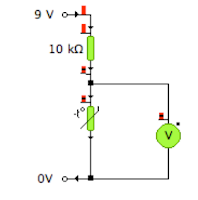
The thermistor is the bottom resistor in a voltage divider.  As the temperature decreases, the resistance of the thermistor will increase.  Therefore the share of the supply voltage dropped over the thermistor will increase (remember the more resistance there is, the more voltage is required) and so the output voltage will increase.  This makes this circuit a cold sensor.

The thermistor is now at the top of the voltage divider.  The properties of the thermistor remain the same (temperature up > resistance down) but because it is now at the top of the voltage divider, the circuit will act as a heat sensor.  As the temperature increases the resistance of the thermistor decreases.  Therefore the share of the voltage dropped over the thermistor will decrease and so the share of the voltage dropped over the fixed resistor must increase and so the output voltage will increase as the temperature increases.

There are different types of thermistor with various temperature ranges.  They are all found on this graph:

This is a "log graph" as in reality the properties of the thermistor will form a curve and not a straight line which is very difficult to read.  So instead this type of graph is used and the axis need to be interpreted.  The temperature axis acts as you would expect and the only difference is the spacing.  The resistance axis, however, is more difficult and this is the bit people get stuck with.  Reading up from the bottom the units read > 10, 20, 30 etc then 100, 200, 300 etc, then 1000, 2000, 3000 etc. 

It is also important to note that the values nearer the top are closer together than those at the bottom.  So a half way point is not half way between the two values, but closer to 1/3 of the value.  i.e. between 1k and 2k, half way would be 1.3k.

To find a value, read along the axis of the value you know (you could be given either the temperature and asked to find the resistance, or the resistance and be asked to find the temperature)  This graph shows that at 25°c the resistance of a type 4 resistor is 50kΩ.
 LDR - Light Dependent Resistor
The light dependent resistor will change resistance as the light level changes.  As the light level increases, the resistance decreases and as the light level decreases, the resistance increases.  LDRs can be used in the same way as thermistors in a voltage divider circuit.

Consider these circuits:

This is a dark sensor - as the light level decreases the resistance of the LDR increases and therefore the voltage dropped over the LDR increases and the voltage out of the voltage divider increases.

This is a light sensor - as the light level increases the resistance of the LDR decreases and therefore the voltage dropped over the LDR decreases so the voltage over the fixed resistor increases and the voltage out of the voltage divider increases.

Just like thermistors there is a graph to show the change of resistance with the change in light level.  This is another log graph so you need to be aware of the axis.  We only need to look at one type of LDR, the ORP12.  You need to be aware that in this graph, the resistance is measured in KΩ.


This graph shows how to read the graph - at a light level of 200 lux the resistance is 600Ω.

It may be necessary to adjust the sensitivity of the circuit, i.e. change the "trigger" temperature or light level.  In this example a signal voltage of 5v is required.  First of all we can use the variable resistor to achieve this voltage at a temperature of 0°c.

We can adjust the temperature which produces that 5v signal voltage to 20°c by changing the resistance of the variable resistor.